Friday, July 16, 2010

Combine Bodies

You can combine multiple solid bodies to create a singled-bodied part or another multibody part. There are three ways to combine multiple solid bodies:
Add. Combines solids of all selected bodies to create a single body.
Subtract. Removes overlapping material from a selected main body.
Common. Removes all material except that which overlaps.
To use the Add or Common operation type:
Click Combine on the Features toolbar, or click Insert, Features, Combine.
The Combine1 PropertyManager appears.
Under Operation Type, click Add or Common.
Under Bodies to Combine, select the bodies in the graphics area, or select the bodies from the Solid Bodies folder in the FeatureManager design tree.
Click Show Preview to preview the feature.
Click OK .
To use the Subtraction operation type:
Click Combine on the Features toolbar, or click Insert, Features, Combine.
The Combine1 PropertyManager appears.
Under Operation Type, click Subtract.
Under Main Body, select the body to keep from the graphics area for Solid Body , or select the body from the Solid Bodies folder in the FeatureManager design tree.
Under Bodies to Subtract, select the bodies whose material you want to remove for Solid Bodies .
Click Show Preview to preview the feature.
Click OK .


For the body intersection multibody technique, you use the Combine feature and its Common option. Body intersection is a quick way to create complex parts with very few operations, which can result in faster performance. The operation takes multiple solid bodies that overlap one another and leaves only the intersecting volumes of the bodies. For most models that can be represented fully by two or three drawing views, this technique can be used by intersecting either two or three extruded solids. The extrusion sketches are the solid lines represented in the two or three views. The following example shows this technique with the intersection of two extrusions.
Front
Top
Isometric
To create the part described above, you begin with the base part:
And then select the Common option of the Combine feature to use only the overlapping material of the base part.
(fr.solidwork help) Read More......

COSMOSXpress

COSMOSXpress offers an easy-to-use first pass stress analysis tool for SolidWorks users. COSMOSXpress can help you reduce cost and time-to-market by testing your designs on the computer instead of expensive and time-consuming field tests.
For example, you may want to examine the effects of a force applied to the faucet. COSMOSXpress simulates the design cycle and provides stress results. It also shows critical areas and safety levels at various regions in the faucet. Based on these results, you can strengthen unsafe regions and remove material from overdesigned areas.
Critical regions
Deformed shape
COSMOSXpress uses the same design analysis technology that COSMOSWorks uses to perform stress analysis. More advanced analysis capabilities are available within the COSMOSWorks line of products. The wizard interface of COSMOSXpress guides you through a five step process to specify material, restraints, loads, run the analysis, and view the results.
The accuracy of the results of the analysis depend on material properties, restraints, and loads. For results to be valid, the specified material properties must accurately represent the part material, and the restraints and loads must accurately represent the part working conditions.
COSMOSXpress supports the analysis of solid, single-bodied parts only. It does not support the analysis of assemblies, surface models, or multibody parts.
After building your design in SolidWorks, you may need to answer questions like:
Will the part break?
How will it deform?
Can I use less material without affecting performance?
In the absence of analysis tools, these questions can only be answered by performing expensive and time-consuming product development cycles. A product development cycle typically includes the following steps:
Build your model in the SolidWorks CAD system.
Prototype the design.
Test the prototype in the field.
Evaluate the results of the field tests.

Modify the design based on the field test results.
This process continues until a satisfactory solution is reached. Analysis can help you accomplish the following tasks:
Reduce cost by testing your model using the computer instead of expensive field tests.
Reduce time to market by reducing the number of product development cycles.
Optimize your designs by quickly simulating many concepts and scenarios before making a final decision, giving you more time to think of new designs.
Stress Analysis
Stress or static analysis calculates the displacements, strains, and stresses in a part based on material, restraints, and loads. A material fails when the stress reaches a certain level. Different materials fail at different stress levels. COSMOSXpress uses linear static analysis, based on the Finite Element Method, to calculate stresses. Linear static analysis makes several assumptions to calculate stresses in the part.
Finite Element Method
The Finite Element Method (FEM) is a reliable numerical technique for analyzing engineering designs. FEM replaces a complex problem with many simple problems. It divides the model into many small pieces of simple shapes called elements.
CAD model of a bracket
Model subdivided into small pieces (elements)
Elements share common points called nodes. The behavior of these elements is well-known under all possible support and load scenarios. The motion of each node is fully described by translations in the X, Y, and Z directions. These are called degrees of freedom (DOFs). Analysis using FEM is called Finite Element Analysis (FEA).
A tetrahedral element. Red dots represent the element's nodes. Element edges can be curved or straight
COSMOSXpress formulates the equations governing the behavior of each element taking into consideration its connectivity to other elements. These equations relate the displacements to known material properties, restraints, and loads.
Next, the program organizes the equations into a large set of simultaneous algebraic equations. The solver finds the displacements in the X, Y, and Z directions at each node.
Using the displacements, the program calculates the strains in various directions. Finally, the program uses mathematical expressions to calculate stresses.
(fr.solidwork help)

Read More......

Saturday, July 10, 2010

Circle

You can sketch a center-based circle with the Circle tool, or you can sketch a perimeter-based with the Perimeter Circle tool.
To create a center-based circle:
Click Circle on the Sketch toolbar, or click Tools, Sketch Entities, Circle.
The pointer changes to .
Click in the graphics area to place the center of the circle.
Move the pointer and click to set the radius.
Click OK .

To create a perimeter-based circle:
Click Perimeter Circle on the Sketch toolbar, or click Tools, Sketch Entities, Circle.
The pointer changes to .
Click in the graphics area to place the perimeter.
Drag left or right to sketch the circle.
When you finished dragging, the pointer is displayed.
Right-click to set the circle.
Click OK .
To modify a circle by dragging:
In an open sketch:
Increase the perimeter by dragging its edge away from its center point.
Decrease the perimeter by dragging its edge toward its center point.
Move the circle by dragging its center point.
To change the properties of a circle:
In an open sketch, select the circle and edit its properties in the Circle
(fr.SOLIDWORK Help)

Read More......

Thursday, July 8, 2010

Extended Surface

Surfaces OverviewSurfaces are a type of geometry that can be used to create solid features. Surface tools are available on the Surfaces toolbar. You can create surfaces by these methods:Insert a planar surface from a sketch or from a set of closed edges that lie on a planeExtrude, revolve, sweep, or loft from sketchesOffset from existing faces or surfacesImport a fileCreate mid-surfacesRadiate surfacesYou can modify surfaces in the following ways:ExtendTrim existing surfacesUntrim surfacesFillet surfacesRepair surfaces using Filled SurfaceMove/Copy surfacesDelete and patch a faceKnit surfaces

You can use surfaces in the following ways:Select surface edges and vertices to use as a sweep guide curve and path.Create a solid or cut feature by thickening a surface.Extrude a solid or cut feature with the end condition Up to Surface or Offset from Surface.Create a solid feature by thickening surfaces that have been knit into a closed volume.Replace a face with a surface You can extend a surface by selecting an edge, multiple edges, or a face.To extend a surface:Click Extended Surface on the Surfaces toolbar or click Insert, Surface, Extend.In the PropertyManager:Under Edges/Faces to Extend, select one or more edges or faces in the graphics area for Selected Face/Edges .For edges, the surface extends along the plane of the edge. For faces, the surface extends along all edges of the face except those connected to another face.You can propagate extended surfaces to tangent faces by clicking the Propagate callout which appears only if you select edges. Select an End Condition type:Distance. Extends the surface by the value you specify in Distance .Up to point. Extends the surface to the point or vertex selected in the graphics area for Vertex .Up to surface. Extends the surface to the surface or face selected in the graphics area for Surface/Face .Select an Extension Type:Same surface. Extends the surface along the geometry of the surface.Linear. Extends the surface tangent to the original surface along the edges.Extend edge using Same surface as the Extension Type.Extend edge using Linear as the Extension Type.Extend surface using the face as the Edges/Faces to Extend and Same surface as the Extension Type.Click OK .
(fr.SOLIDWORK Help)
Read More......

Wednesday, June 16, 2010

text extrude

You can sketch text on the face of a part and extrude or cut the text. The text can be inserted on any set of continuous curves or edges, including circles or profiles made up of lines, arcs, or splines.
If the curve is a sketch entity, or a set of sketch entities, and the sketch text is in the same sketch as the curve, convert the sketch entities to construction geometry.
To sketch text on a part:
Click a face of a part.
Click Text on the Sketch toolbar, or click Tools, Sketch Entities, Text.

To create a profile for placing the text, sketch a circle or a continuous profile from lines, arcs, or splines in a sketch, close the sketch, then open another sketch for the text.
In the graphics area, select an edge, curve, sketch, or sketch segment.
The selected item appears under Curves .
In the PropertyManager, under Text, type the text to display.
The text appears in the graphics area as you type.
Set the properties in the Sketch Text PropertyManager as necessary.
Click OK .
With the sketch still open, Extrude or Cut the text.
To edit sketch text:
In an open sketch, right-click the text (the pointer changes to when it is over the sketch text) and select Properties.
Edit the text and its properties in the Sketch Text PropertyManager as necessary.
(fr.SOLIDWORK Help)
Read More......

Monday, June 14, 2010

Split feature

Use the Split feature to create multiple parts from an existing part. You can create separate part files, and form an assembly from the new parts. You can split a single part document into a multibody part document.
To split a part:
Click Split on the Features toolbar, or click Insert, Features, Split.
In the PropertyManager, under Trim Tools, select one or more of the following for Trimming Surfaces :
Reference planes (Planes extend infinitely in all directions.)
Planar model faces (Faces extend infinitely in all directions.)

Original Part
Revised Original Part
New Part
Sketches (Sketches extrude through all in both directions.)
Original Part
Revised Original Part
New Part
Reference surfaces and non-planar model faces (These do not extend their boundaries. Internal holes on reference surfaces or non-planar model faces are closed when splitting the part.)
Original Part
New Parts
Click Cut Part.
Split lines appear on the part, showing the different bodies formed by the split.
Callout boxes appear in the graphics area for up to 10 bodies at one time. Click Next 10 or Previous 10 to scroll through all the callout boxes for a part.
Under Resulting Bodies, select the bodies to save under , then select one of the following for Resultant bodies state:
Show bodies. All bodies appear in the graphics area. All of the bodies are listed in the FeatureManager design tree under Solid Bodies, and the icons are filled .
Hide bodies. Only the bodies that you did not split appear in the graphics area. Bodies that are selected are hidden. All the split bodies are listed in the FeatureManager design tree under Solid Bodies, but the icons for hidden bodies are blank .
Consume bodies. Removes the body from the part. Consumed bodies are not listed in the FeatureManager design tree under Solid Bodies.
Double-click the body name under File, type a name for the new part in the dialog box, then click Save.
The new part name appears in the Resulting Bodies list and in the callout box. The bodies that you do not save are not split. They remain with the original part.
If you clear the check box for a split part after you save it, that part is no longer saved as a separate entity. It remains with the original part.
You can choose the same name for two different bodies if they are identical. If the bodies are not identical, the software does not let you choose the same name.
Click OK .
New Parts
The new parts are derived; they contain a reference to the parent part. Each new part contains a single feature named Stock--n->.
If you change the geometry of the original part, the new parts also change.
With multibody parts, the various split parts are listed in the FeatureManager design tree under Solid Bodies.
Original Part
The original part contains all its original features plus a new feature called Split.
If you selected Hide bodies or Consume bodies under Resultant bodies state, the solid body displayed in the graphics area is the original solid body minus the new parts. If all bodies in the original part were saved as split bodies, no solid body is displayed. To see the original solid body, move the rollback bar in the FeatureManager design tree above the split feature or suppress the split feature.
If you delete the split feature in the original part, the new parts still exist, but the status of the external reference in the new parts is dangling.
You can also save solid bodies after you split the model using the Save Bodies feature. This enables you to save the bodies from a split part to a different folder or with different names to the same folder. You can also create an assembly from the split parts.
To save bodies from multibody parts:
Click Insert, Features, Save Bodies.
Select the bodies to save in the graphics area, or under in Resulting Parts.
The callouts display the default path, file names, and location of the multibody part.
Under Resulting Parts, double-click each file name under File to open the Save As dialog box. You can select a new location and file name for each part.
To create an assembly, under Create Assembly, click Browse, select a folder to save the assembly as SplitAssembly type (*.sldasm), and type a file name.
Click OK .
(fr.solidwork.help)

Read More......

Saturday, June 12, 2010

Sketching a Boss

To create additional features on the part (such as bosses or cuts), you sketch on the model faces or planes, then extrude the sketches.

You sketch on one face or plane at a time, then create a feature based on one or more sketches.

Click Hidden Lines Removed on the View toolbar.

Click Extruded Boss/Base on the Features toolbar.

Move the pointer over the front face of the part.

The pointer changes to , and the edges of the face become highlighted to show that the face is available for selection.


Select the front face of the part.
A sketch opens on the front face of the part. The Sketch toolbar commands appear in the CommandManager.
Sketching a Boss (continued)
Click Circle on the Sketch toolbar.
The pointer changes to .
Click near the center of the face and move the pointer to sketch a circle. Click again to complete the circle.
Dimensioning and Extruding the Boss
To establish the location and size of the circle, add the necessary dimensions.
Click Smart Dimension on the Sketch toolbar.
Select the top edge of the face, select the circle, then click a location for the dimension.
A closer look at dimensioning
Double-click the dimension, set the value to 60 in the Modify dialog box, and click to dimension the circle to the top edge of the face.
Repeat the process to dimension the circle to the side edge of the face. Set this value to 60.
Dimensioning and Extruding the Boss (continued)
Still using Smart Dimension , select the circle to dimension its diameter. Move the pointer around to see the preview for the dimension.
When the dimension is aligned horizontally or vertically, it appears as a linear dimension; if it is at an angle, it appears as a diameter dimension.
Click a location for the diameter dimension. Set the diameter to 70. Add the two other dimensions as shown.
The circle turns black, and the status bar indicates that the sketch is fully defined.
Click Exit Sketch on the Sketch toolbar.
The Extrude PropertyManager appears.
In the PropertyManager, under Direction 1, set Depth to 25, leave the other items at the defaults, and click OK to extrude the boss feature.
Extrude2 appears in the FeatureManager design tree.

(fr,solidwork help)

Please see below to simple application


Read More......

Tuesday, June 8, 2010

Creating the Base


You can capture the symmetry of the knob in the design intent of the part. You build one half of the sample part in this tutorial, then in the Fillet Features tutorial, you mirror the model to create the other half. Any changes you make to the original half are reflected in the other half.


When you relate features to the origin and the planes, you need fewer dimensions and construction entities, and you can more easily modify the

part.


Click New on the Standard toolbar and open a new part.


Click Extruded Boss/Base on the Features toolbar and open a sketch on the Front plane.


Click Centerpoint Arc on the Sketch toolbar.


Drag downward from the origin, then release the pointer.

A circumference guideline appears.


Click and drag an arc 180° counterclockwise around the origin.


The pointer changes to when a 90°, 180°, or 270° arc exists.


Connect the arc endpoints with a vertical line.

Dimension the arc radius .


Now you add relations and create an extrude feature.

Click Select on the Standard toolbar, hold down Ctrl, then select the vertical line and the origin.


The Properties PropertyManager appears.


Under Add Relations, click Midpoint , then click OK .


The line is now fully defined.


Click Exit Sketch on the Sketch toolbar.


The Extrude PropertyManager appears.


Under Direction 1:


Select Blind in End Condition.


Set Depth to 40.


Click OK to create the extrude

(fr. solidwork help)


Read More......

Saturday, June 5, 2010

The Extrude

The Extrude PropertyManager defines the characteristics of extruded features. You can create these types of extruded features:
Type of Extrude
Solid or thin
Boss/base
Cut
urface
To create an extrude feature:
reate a sketch.
Click one of the extrude tools:
Extruded Boss/Base on the Features toolbar, or click Insert, Boss/Base, Extrude
Extruded Cut on the Features toolbar, or click Insert, Cut, Extrude
Extruded Surface on the Surfaces toolbar, or click Insert, Surface, Extrude
Set the PropertyManager options.
To extrude in both directions from the sketch plane, set the PropertyManager options in Direction 1 and Direction 2. To extrude as a thin feature, set the PropertyManager options in Thin Feature.
Click OK .
(fr.solidwork help) Read More......

Friday, June 4, 2010

Extended Surface

Surfaces Overview
Surfaces are a type of geometry that can be used to create solid features. Surface tools are available on the Surfaces toolbar. You can create surfaces by these methods:
Insert a planar surface from a sketch or from a set of closed edges that lie on a plane
Extrude, revolve, sweep, or loft from sketches
Offset from existing faces or surfaces
Import a file
Create mid-surfaces
Radiate surfaces
You can modify surfaces in the following ways:
Extend
Trim existing surfaces
Untrim surfaces
Fillet surfaces
Repair surfaces using Filled Surface
Move/Copy surfaces
Delete and patch a face
Knit surfaces
You can use surfaces in the following ways:
Select surface edges and vertices to use as a sweep guide curve and path.
Create a solid or cut feature by thickening a surface.
Extrude a solid or cut feature with the end condition Up to Surface or Offset from Surface.
Create a solid feature by thickening surfaces that have been knit into a closed volume.
Replace a face with a surface

You can extend a surface by selecting an edge, multiple edges, or a face.
To extend a surface:
Click Extended Surface on the Surfaces toolbar or click Insert, Surface, Extend.
In the PropertyManager:
Under Edges/Faces to Extend, select one or more edges or faces in the graphics area for Selected Face/Edges .
For edges, the surface extends along the plane of the edge. For faces, the surface extends along all edges of the face except those connected to another face.
You can propagate extended surfaces to tangent faces by clicking the Propagate callout which appears only if you select edges.
Select an End Condition type:
Distance. Extends the surface by the value you specify in Distance .
Up to point. Extends the surface to the point or vertex selected in the graphics area for Vertex .
Up to surface. Extends the surface to the surface or face selected in the graphics area for Surface/Face .
Select an Extension Type:
Same surface. Extends the surface along the geometry of the surface.
Linear. Extends the surface tangent to the original surface along the edges.
Extend edge using Same surface as the Extension Type.
Extend edge using Linear as the Extension Type.
Extend surface using the face as the Edges/Faces to Extend and Same surface as the Extension Type.
Click OK .
(fr.solidwork help) Read More......

Thursday, June 3, 2010

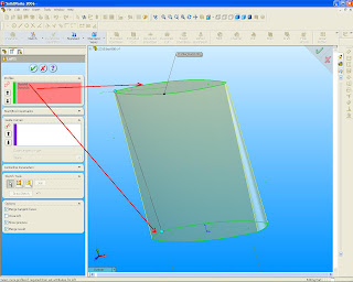
create a loft

Loft creates a feature by making transitions between profiles. A loft can be a base, boss, cut, or surface. You create a loft using two or more profiles. Only the first, last, or first and last profiles can be points. All sketch entities, including guide curves and profiles, can be contained in a single 3D sketch.
For a solid loft, the first and last profiles must be model faces or faces created by split lines, planar profiles, or surfaces.
To create lofts:
Do one of the following:
Click Loft on the Features toolbar, or click Insert, Boss/Base, Loft.
Click Lofted Cut on the Features toolbar, or click Insert, Cut, Loft.
Click Lofted Surface on the Surfaces toolbar, or click Insert, Surface, Loft.
Set the options in the PropertyManager.
Manipulate the loft these ways:
Synchronize loft profiles.
Use Sketch Tools in the PropertyManager to select contours.
Drag 3D sketch geometry to change the feature's shape when you create or edit a loft.
Add, position, and edit new loft sections.
Create a loft to a point, even if the point is part of a sketch containing other sketch entities.
View the loft using zebra stripes as you create it.
Place the pointer on the loft, open the shortcut menu, and select Zebra stripes preview. When you create another sweep, loft, or add a loft section, the zebra stripes display. Use the shortcut menu to clear Zebra stripes preview.
View the loft using a mesh preview.

Set the PropertyManager options based on the type of loft feature. See Loft Overview for more information about lofts.
Profiles
Profile . Determines the profiles used to create a loft. Select sketch profiles, faces, or edges to connect. Lofts are created based on the order of profile selection.
For each profile, select the point from which you want the path of the loft to travel.
Move Up and Move Down . Adjusts the order of the profiles. Select a Profile and adjust the profile order.
If the loft preview shows an undesirable loft, re-select or reorder the sketches to connect different points on the profiles.
Start/End Constraints
Start constraint and End constraint. Applies a constraint to control tangency to the start and end profiles. The options are:
Default. Approximates a parabola scribed between the first and last profiles. The tangency from this parabola drives the loft surface, which results in a more predictable and natural loft surface when matching conditions are not specified.
None. No tangency constraint (zero curvature) is applied.
Direction Vector. Applies a tangency constraint based on a selected entity used as a direction vector. Select a Direction Vector , then set the Draft angle and Start or End Tangent Length.
Normal to Profile. Applies a tangency constraint normal to the start or end profile. Set the Draft angle and Start or End Tangent Length.
Tangency to Face (Available when attaching a loft to existing geometry). Makes the adjacent faces tangent at the selected start or end profile.
Curvature to Face (Available when attaching a loft to existing geometry). Applies a smooth, visually appealing curvature continuous loft at the selected start or end profile.
Next Face (Available with Tangency to Face or Curvature to Face selected for Start or End constraint). Toggles the loft between available faces.
Direction Vector (Available with Direction Vector selected for Start or End constraint). Applies a tangency constraint based on a selected entity used as a direction vector. The loft is tangent to the selected linear edge or axis, or to the normal of a selected face or plane. You can also select a pair of vertices to set the direction vector.
Draft angle (Available with Direction Vector or Normal to Profile selected for Start or End constraint). Applies a draft angle to the start or end profile. If necessary, click Reverse Direction . You also apply a draft angle along guide curves.
To set the Draft angle, you can also use a design table, or you can double-click the loft feature in the FeatureManager design tree to display the values in the graphics area.
Start and End Tangent Length (Not available with None selected for Start or End constraint). Controls the amount of influence on the loft. The effect of tangent length is limited up to the next section. If necessary, click Reverse Tangent Direction .
Apply to all. Displays one handle that controls all the constraints for the entire profile. Clear this option to display multiple handles that permit individual segment control. Drag the handles to modify the tangent length.
(fr.solidwork help) Read More......

Wednesday, June 2, 2010